
Brass Knurled Expansion Insert
Technical and Manufacturing Guide
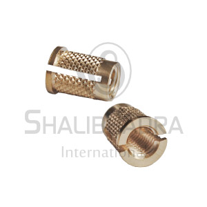
A brass knurled expansion insert is a threaded metal component designed to provide a secure screw connection in a compatible host material, commonly plastic. Its outer surface has a knurled pattern—small ridges, teeth or grooves—that helps the insert grip the surrounding material and resist rotation or pull-out.
The word expansion may refer to a specific mechanism that expands the insert during installation, or it may be used more generally for an insert that develops a tight fit in a prepared hole. The exact product drawing determines which mechanism applies.


Main components
A. Internal thread
Receives the mating screw or bolt. Metric thread sizes such as M3, M4, M5, M6 and M8 are common across insert product families, but availability depends on the design.

B. External knurling
A patterned surface that increases mechanical engagement with the surrounding material. Straight, diamond and angled patterns are possible.

C. Lead-in and body geometry
Chamfers, tapered ends, shoulders or slots can help with alignment, insertion depth or expansion. These features must match the intended installation method.

Typical specifications
The following table gives general engineering options for this product category. It is not a verified specification for a particular manufacturer or part number.
| Parameter | Typical options |
|---|---|
| Material | Free-machining brass or specified low-lead brass |
| Internal thread | Metric or inch-based thread |
| Thread sizes | Commonly M3–M8 in various product families |
| Knurl pattern | Straight, diamond, angled or custom |
| Body shape | Cylindrical, tapered or shouldered |
| Installation | Thermal, ultrasonic, press-fit or designed expansion method |
| Surface finish | Natural brass or specified plating |
| Manufacturing | CNC turning, automatic lathe machining, knurling, drilling and tapping |
Not every insert supports every installation method. A standard knurled insert should not be assumed to be an expansion-type insert without confirming its geometry.
How the knurled surface works


-
Straight knurling: Produces longitudinal ridges that can help resist rotation.
-
Diamond knurling: Produces intersecting ridges that create multidirectional mechanical engagement.
-
Angled or helical knurling: May improve retention depending on the direction of applied loads and the host material.
-
Tapered or expansion features: May generate radial pressure during installation if the insert is specifically designed for that purpose.
The best pattern depends on the resin or other host material, installation method, required pull-out force and torque resistance.
Applications

Plastic housings and electronic products
Creates reusable screw threads for covers, circuit-board supports and equipment enclosures.

Provides a threaded attachment point in compatible moulded parts, subject to temperature, vibration and load requirements.
Furniture and consumer products
Helps support repeated assembly and disassembly without relying on threads formed directly in soft material.
Manufacturing process for brass knurled expansion inserts


A typical production route is:
-
Raw material selection: Select a brass alloy appropriate for machining, strength and applicable lead-content requirements.
-
Bar feeding and facing: Feed brass bar into a CNC or automatic turning machine and face the end.
-
External turning: Machine the outside diameter, shoulder, chamfer and any tapered profile.
-
Knurling: Form the specified straight, diamond or other knurl pattern using suitable tooling or a machining operation.
-
Drilling and tapping: Produce the internal hole and thread to the specified depth and tolerance.
-
Parting and deburring: Separate the component and remove burrs without damaging the knurl or thread.
-
Finishing and inspection: Clean or plate the insert if required, then verify dimensions, thread fit and retention performance.
For high-volume manufacturing, the key variables are machining cycle time, knurl-tool life, chip evacuation, tapping reliability and rejection rate. The actual operation sequence depends on whether the insert has a through-hole, blind hole, taper, slot or active expansion mechanism.
Example dimensions for preliminary design
The following is an illustrative example for an M6 knurled insert, not a manufacturer’s drawing.
| Feature | Example value |
|---|---|
| Internal thread | M6 × 1.0 |
| Body outside diameter | 8 mm |
| Overall length | 10 mm |
| Threaded depth | 8 mm |
| Lead-in chamfer | 0.3–0.5 mm |
| Knurl profile | To be defined on drawing |
| Material | Specified brass grade |
The correct body diameter, knurl depth and installation-hole diameter depend on the specific insert design and host material. Do not use these example dimensions directly for production without testing.
Quality control and performance testing
| Test | Purpose |
|---|---|
| Thread GO/NO-GO gauge | Checks internal thread conformity |
| Outside-diameter measurement | Verifies fit and body size |
| Knurl inspection | Checks pattern, depth and consistency |
| Installation-force test | Measures the force needed to install the insert |
| Pull-out test | Measures resistance to axial extraction |
| Torque-out test | Measures resistance to rotation |
| Assembly test | Checks screw installation and thread durability |
For plastic applications, test the actual resin, wall thickness and installation method. Excessive insertion force can crack the plastic, while insufficient interference may cause rotation or pull-out.
Related Product
Explore the Product
Discover more details about the product featured in this article.
View Product